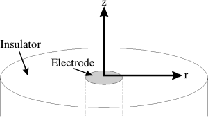
Figure 2.1: Microdisc electrode

The basic principles of finite differences were introduced in Chapter 1. In this chapter it is shown how electrochemical material balance equations may be approximated by several subtly different finite difference discretisation schemes. The relative merits of these schemes, each offering varying amounts of 'implicitness', are discussed. The result of discretisation is a set of linear or possibly non-linear simultaneous equations, to which boundary conditions (defining the edges of the cell, position/nature of the electrode etc.) must be applied. The remainder of the chapter addresses the solution of these equation systems, ending with how non-linear problems may be linearised allowing one of the standard linear solvers to be applied.
Consider a typical time-dependent mass-transport equation, such as that to a microdisc electrode, shown in Figure 2.1:
 |
(2.1) |
If this is approximated using (central) finite differences it becomes:
 |
(2.2) |
where u represents the discrete concentration values on the finite difference grid. This may be written in the general form:
 |
(2.3) |
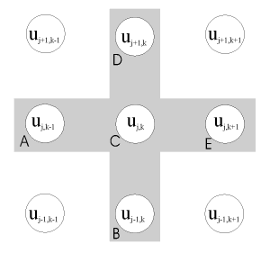
where Aj,k ... Ej,k are known coefficients [D/(Dz)2 etc. for the microdisc electrode]. The five-point star spanned by the coefficients Aj,k ... Ej,k is known as a 'stencil', shown in Figure 2.2. This general form applies to the mass transport equation for many of the geometries discussed in this thesis (although for systems where mass transport may be described as a function of a single spatial dimension, the equation is simplified as the coefficients Ajk and Ejk are zero).
There is a choice as to whether the concentrations on the right-hand side are chosen to be at t or t+1. If concentrations at the old time (t) are used we have an explicit equation:
 |
(2.4) |
This may be written more generally as a matrix equation:
 |
(2.5) |
where the unknown, u = ut+1, b = ut (the known vector of concentrations) and M is a matrix of coefficients (composed of Aj,k ... Ej,k for all j and k).
On the other hand, one could choose to represent the concentrations on the right-hand side of equation (2.3) as at (t+1), in which case the resulting equation is implicit:
 |
(2.6) |
Again this linear system of equations by be written in matrix form as:
 |
(2.7) |
This is not as straightforward as the explicit case, so why bother? The implicit equations are unconditionally stable, whereas the explicit equations break down if the time step is too large. The extra accuracy and efficiency of an implicit method may offset the CPU overhead of solving the linear system using an iterative method, rather than the Thomas Algorithm with a semi-explicit scheme (see below). This is especially true if only the steady-state solution is required1.
The third option is to mix the explicit and implicit methods. We can write the equation as:
 |
(2.8) |
where a is an adjustable parameter which varies between 0 (fully explicit) and 1 (fully implicit). When a=0.5 this is known as the Crank-Nicolson (CN) method. The matrix equation is the same as for the fully implicit method:
 |
(2.9) |
The Crank-Nicolson method (essentially being equivalent to a central time difference) is less stable but more accurate than the fully implicit scheme345-6 (which may be regarded as an upwind discretisation). Störzbach and Heinze7 recommend this method for general 1D simulations. Britz8 reported improved efficiency by incorporating Crank-Nicolson discretisation into Rudolph's FIFD method.
Taking the Crank-Nicolson idea one step further, if we have already computed the solution vectors for a few time steps, we should be able to use this information to predict the next vector more accurately using a higher order backward difference formula. Feldberg and co-workers10,11 have used this approach for 1-D diffusion simulations, including with Rudolph's FIFD method (see section 2.6.1.3), finding a significant improvement in efficiency and stability. The difference formulae (used by Feldberg et al.) are:
2 point:  3 point:  4 point:  5 point:  |
(2.10) |
Feldberg and Goldstein11 gave the following equations:
 and and
 |
(2.11) |
which allow the coefficients (c0...cn-1) to be calculated for an n-point Taylor expansion. Britz12,13 has done stability analysis on 3-7 point formulae, finding them all unconditionally stable. Strutwolf and Schoeller14 used a closely-related extrapolation method which has the additional advantage that it does not require 'starting' values. They compared this to Crank-Nicolson and fully implicit formulae for 1-D diffusion-kinetics problems, finding it superior.
This 'trick', also based on considering multiple time steps, has been used to improve the efficiency of explicit simulations by Feldberg16,17-18 who coined the acronym FQEFD (fast quasi-explicit finite difference) for its application in electrochemistry. It is based on the assumption that uj,k is a linear function of t:
 |
(2.12) |
This may be substituted into the explicit finite difference equation:
 |
(2.13) |
The resulting explicit equation is much more stable19 than the simple explicit case, enabling larger time steps to be used.
This method is another way of introducing some implicit 'character' into an explicit simulation. The method works by solving every other node explicitly, then solving the nodes in-between. It has been used mainly for two-dimensional simulations, which may be visualised as a chessboard21. Initially all the white squares (odd nodes) are solved explicitly:
 |
(2.14) |
The black squares (even nodes) are then solved using the implicit equation:
 |
(2.15) |
However, since the concentration has already been solved for at the 4 white stencil points, this expression may be evaluated explicitly:
 |
(2.16) |
In general the equation may be written:
 |
(2.17) |
'Fast' Hopscotch is derived by considering a second step:
 |
(2.18) |
Substituting (2.17) into (2.18) gives:
 |
(2.19) |
which for odd nodes, simplifies to:
 |
(2.20) |
The algorithm is fully explicit but unconditionally stable and thus time steps of any size may be used. However the accuracy of the simple explicit method is barely improved upon3. The method was introduced into electrochemistry by Shoup and Szabo22 for microdisc simulations and was subsequently adopted by many other electrochemists23. Feldberg24 pointed out that the method has disadvantages when simulations involve boundary singularities (see Chapter 3 for more details about these). For example in potential step chronoamperometry the current is infinite at the moment when the potential is stepped. The discrete time grid cannot 'cope' with such an abrupt change and an error propagates for several time steps. Since only half the nodes are solved in each 'step' in Hopscotch, the error propagation is much worse.
For simulations in more than one dimension, there is another option for an implicit mix: one may choose to treat one co-ordinate implicitly and the others explicitly. This is done alternately, so each co-ordinate has a 'share' of the implicit iterations, known as an 'Alternating Direction Implicit' method. In two dimensions, for odd time steps the finite difference equation is:
 |
(2.21) |
and for even time steps:
 |
(2.22) |
The method was used by Heinze and co-workers for microdisc simulations26 and has subsequently been adopted by others27-282930. Gavaghan and Rollett31 compared it to Hopscotch for simulating chronoamperometry at a microdisc electrode and found that ADI is more accurate for a given mesh size.
Often, especially when using hydrodynamic or microelectrodes, only the steady-state response of the system need be simulated, so the time-dependent equation can be simplified to:
 |
(2.23) |
(using the microdisc example). The finite difference representation becomes:
 |
(2.24) |
Once again this may be represented as the matrix equation:
 |
(2.25) |
where all the elements of b are zero.

In some hydrodynamic electrodes, rapid convection occurs perpendicular to the electrode surface so that diffusion is negligible in that co-ordinate. Such behaviour occurs at high flow rates in the wall-jet electrode or channel flow-cell (Figure 2.3) where the mass transport at steady-state is given by:
 |
(2.26) |
This may be discretised as:
 |
(2.27) |
(where l=D/vx) which may be represented by the matrix equation:
| [Tri]u = b | (2.28) |
where [Tri] is a tridiagonal matrix. The algorithm sweeps along k in a 'frontal' fashion, with each vector being computed from the previous one (note that throughout this thesis, the phrase 'Backwards Implicit' and acronym BI refer to this space-marching application of the implicit method). The time-dependent mass transport equation:
 |
(2.29) |
may be discretised as:
 |
(2.30) |
(where lV = Dt.vx and lD = Dt.D). If this is solved for all k at t+1, then at t+2 etc. it still conforms to the matrix equation:
| [Tri]u = b | (2.31) |
since both  and
and  are known and may be used to
form b. This is known as the time-dependent or transient BI
method35.
Once the mass transport equation has been converted into a system of finite difference equations, the boundary conditions must be applied. For boundary conditions which define a value of the concentration (Dirichlet boundaries), this is trivial. For example, in the channel flow-cell a boundary condition corresponding to complete electrolysis:
| 0 < x < xe; e; y = 0: [A] = 0 | (2.32) |
may be implemented as (assuming simulations are conducted using normalised concentrations)
| u0,k = 0 for k=1 ... kE | (2.33) |
Thus equation (2.27) at j=1 would become:
 |
(2.34) |
Where the boundary condition is defined in terms of a derivative (Neumann boundaries), namely a flux for electrochemical simulations, the derivative in the boundary equation must be expressed as a finite difference so that it may be incorporated into the linear system. For example, in the channel flow-cell there is a "no-flux" boundary on the cell wall at the top of the channel:
y = 2h:  |
(2.35) |
which may be implemented (using a first-order difference formula) as:
 (
uNGY = uNGY-1 (
uNGY = uNGY-1 |
(2.36) |
Thus equation (2.27) at j=NGY would become
 |
(2.37) |
In section 3.8, higher-order difference formulae are discussed.
As discussed in Chapter 1, these are reactions (chemical or electrochemical) which occur on the electrode surface and therefore define the electrode surface boundary condition. For a quasi-reversible couple, these boundary conditions are a composite of the electrochemical kinetics:
 where where  ; ;
 |
(2.38) |
and a conservation of flux:
 assuming D=DA=DB assuming D=DA=DB |
(2.39) |
Both these equations contain derivatives which must be converted into finite difference form, thus:
 |
(2.40) |
Solving these equations simultaneously, one can obtain expressions for the surface concentrations of each of the species in terms of the concentrations at one node above the electrode surface:
 and and
 |
(2.41) |
When the couple is fully reversible, these simplify to:
 and and
 |
(2.42) |
When chemical reactions occur in solution, terms are added to the material balance equations. For example, consider an irreversible EC2E process:

at a microdisc electrode, where the mass-transport/kinetic equations are:
   |
(2.43) |
(where kEC2E = k[A]bulk if a, b and c are normalised concentrations).
If, as in this example, one of the chemical reactions is second-order, the resulting finite difference equation(s) are non-linear. Thus for species B:
 |
(2.44) |
where k represents the kinetic coefficient (including the factor of 2). This cannot be solved using one of the 'standard' linear solvers described below. In the last section of this chapter, methods are described for the solution of such non-linear equation systems.
Chemical reactions couple the matrix equations for each species so they cannot be solved independently. The easy way around this is to approximate the kinetic terms explicitly (using concentrations at the old time), for example in an EC2E mechanism species C is made from species B. The finite difference equation for species C could therefore use the concentration of species B from the previous time step:
 |
(2.45) |
This also restores the linearity of the right-hand-side - the non-linear term is simply evaluated and added into b. Unfortunately this explicit approximation breaks down at high rate constants requiring ever smaller time steps to keep the simulation stable as the rate constant increases. This is discussed further in section 3.7.
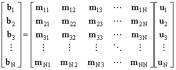
The system of simultaneous equations:
 |
(2.46) |
may be solved by either direct methods such as Gaussian elimination (or by simply calculating the inverse of the coefficient matrix, M) or iterative methods36 such as Gauss-Seidel iteration.
The main problem with treating the linear system of finite difference equations as a matrix is that most of the elements are zero. Most two-dimensional problems are based on a 5-band matrix (arising from the 5 point mass transport stencil) with an additional band for each relation of one species to another via the homogenous and heterogeneous kinetic equations.
Britz37 has coined the phrase 'brute force' for the application for a method such as Gaussian elimination to solve the entire system, and when one considers the order of such a matrix this becomes apparent. A very modest two-dimensional finite difference simulation may have a grid of 200 x 200 nodes. A simple mechanism such as ECE may require simulation of 4 species. This gives rise to a matrix of order 160,000 (25.6x10⁹ elements). This would require 191GB of memory to store as double precision floating-point values and a vast amount of CPU time to invert. When Britz used direct LU decomposition to perform the inversion37, he only tackled one-dimensional problems and a single species two-dimensional diffusion-only microdisc problem using an efficient conformal mapping which allowed a simulation grid of 30x30 nodes.
The obvious solution is to use a sparse-matrix method which does not store or operate on the zero elements. For the case where M is tridiagonal, the Gaussian elimination process simplifies to the Thomas Algorithm. This is probably the most common solution method for linear systems to appear in the electrochemical literature. Most iterative methods can be adapted for a specific sparsity pattern and these therefore dominate the remainder of the literature, although Georgiadou and Alkire38 used a non-linear frontal (direct) sparse solver39 for the simulation of etching of copper foil.
Gaussian elimination40 is an automated way of solving a large set of simultaneous equations, by subtracting multiples of one equation from another (eliminating) until one equation can be solved, then back-substituting, to find all the other unknowns. If the coefficient matrix is not diagonally dominant, then pivoting (usually by selecting the largest element in a row as the coefficient to divide by, and sometimes by scaling the rows) can be used to improve the accuracy and avoid division by zero. The elimination process is equivalent to a (Doolittle) LU decomposition since the reduced equations form the upper triangular (U) and the multipliers used in the elimination procedure form the unit lower triangular matrix (L).
 |
(2.47) |
The time taken for the LU decomposition is proportional to the number or elements in M - the square of the number of equations. Of course L need not be stored, but if the same matrix needs to be operated on multiple right-hand-sides, once L and U have been computed/stored, only back substitution need be performed on each RHS (see the Thomas Algorithm below as an example of this).
Gaussian elimination library routines are abundant - for example the F04A routines or F11DBF (for sparse matrices) in the NAG FORTRAN library41.
For a tridiagonal matrix, Gaussian elimination simplifies to a procedure known as the Thomas Algorithm. The Gaussian elimination algorithm is essentially:
| 1. LU Decomposition: d = Mu; M
= LU 2. Back-substitution through an intermediate vector: d = Lf thus f = L-1d 3. Forward-substution to give the solution: f = Uu thus u = U-1f |
(2.48) |
1. An LU factorisation of the tridiagonal is of the form:
 |
(2.49) |
By considering the multiplication of L and U:
| bj = ajbj-1 + aj and b1 = a1 thus aj = bj - ajbj-1 and a1=b1 cj = bjaj thus bj = cj/aj |
(2.50) |
Thus the values of a and b may be computed in the order 1,2,...,N.
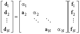
2. Back-substitution is accomplished through the intermediate stage:
 |
(2.51) |
Inspecting the multiplication allows inversion of L 'by hand'
| dj = ajfj-1 + ajfj and d1 = a1f1 thus fj = (dj-ajfj-1)/aj and f1=d1/a1 | (2.52) |
Thus values of f may be computed in the order 1,2,...,N.
3. The final step:
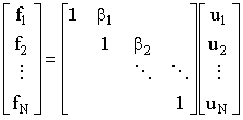 |
(2.53) |
Again, inspecting the multiplication gives the effective inverse of U
| fj = uj + bj+1uj+1 and fN = uN thus uj = fj - bj+1uj+1 and uN = fN | (2.54) |
Thus values of u may be computed in the order N,N-1,...,1.
The Thomas Algorithm is a very efficient way of solving tridiagonal linear systems and is therefore the solver of choice for most one-dimensional simulations. It is also useful for 2-dimensional simulations which have been discretised by an ADI scheme leading to a tridiagonal linear system. The other case where it is commonly applied is in the 2-D frontal BI method for ChE or WJE simulations. In this method, which "marches" along the electrode (in the x-co-ordinate), the same matrix occurs with a number of different right-hand-sides (d). In this case the LU-decomposition part of the Thomas Algorithm only needs to be done once - solution in the k-loop (across the electrode) then consists of one forwards (calculating f) and one backwards loop (calculating u) in j.
This is a block form of the Thomas Algorithm proposed by Rudolph which may be used for the simulation of multi-species problems in one spatial dimension. It is the algorithm used in the commercial simulator DigiSim(tm)45.
Consider a three species problem, where the mass-transport for each species may be discretised using a three point stencil onto a grid of NJ nodes. The fully-implicit finite difference equation in the absence of kinetics is:
 |
(2.55) |
As shown above, all three species can be mapped into a linear system with a tridiagonal coefficient matrix. If we order the system of linear equations so that the elements for various species at a given grid node are adjacent we get:
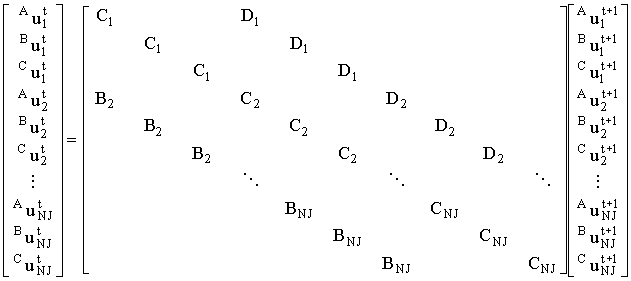 |
(2.56) |
This may be condensed into block form:
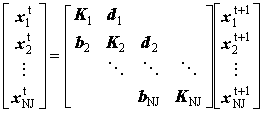 |
(2.57) |
where
 , ,
 , ,  and and  |
(2.58) |
Applying a matrix version of the Thomas Algorithm (using square brackets to denote matrices) we get:
| LU factorisation: [a]j = [K]j - bj
[b]j-1 but [a]1 =
[K]1 and [b]j = dj [a]j-1 |
(2.59) |
Forward sweep  but but  |
(2.60) |
Backward sweep  but but  |
(2.61) |
In fact Rudolph44 substitutes the matrix [b]j into the first and third expression and performs the sweeps in the opposite direction, but this is a matter of personal choice. For the no kinetics case, [a]j-1 is diagonal and its inverse is trivial. When kinetic terms are added (e.g. for an irreversible ECE process):
 |
(2.62) |
and
 |
(2.63) |
these fill each block matrix:
 |
(2.64) |
where lk = kDt. Now each of the associated block matrices, [a]j, have off diagonal terms and must be inverted by LU factorisation. Since these are small, this is relatively efficient, though iterative refinement of the solution may be desirable to prevent error propagation.
In an iterative scheme the unknown concentration vector (u) is solved from a starting approximation. Given an approximation of u, the method generates an improved approximation u'. Iterations continue until the change between iterations, or norm of the residual is lower than a threshold value.
Perhaps the most intuitive iterative scheme is to rearrange each linear equation for xi thus creating an expression for each element of the solution vector. For example for our 5-point steady-state finite difference equation (2.24) we would get:
 |
(2.65) |
These equations can be used to generate the new value of each element from the old vector:
 |
(2.66a) |
or for a general linear system:
 |
(2.66b) |
where ui = uj,k (related through some storage map equation such as i = j + [NGY - 1]k ), bi are the rows in b, mih are elements of M, as shown in (2.47).
An improvement on the Jacobi method is to use the new values of ui we have already computed (u1 - ui-1) for the current approximation, ui. Thus:
 |
(2.67) |
where N is the number of equations, but
 |
(2.68) |
and
 |
(2.69) |
thus in the 5-point stencil:
 |
(2.69b) |
This method has been used for electrochemical simulations46, though in light of the more efficient alternatives below, it is not recommended47.
A similar philosophy to the Crank-Nicolson method is that for an iterative scheme
| u' = u + e | (2.70) |
it may be possible to generate a better approximation, u" from a composite of the new approximation and the previous one:
| u" = wu' + (1-w)u | (2.71) |
The rate of convergence is critically dependant on w. For model problems the optimal value of w can be calculated, but for real-life problems w usually has to be found empirically. When w> 1 this is known as Successive Over-Relaxation (SOR) (usually applied to the Gauss-Seidel iteration). This method was used by Gavaghan49 for simulations of the steady-state response of a microdisc electrode and offers a significant improvement in the convergence rate over Gauss-Seidel. Prentice and Tobias50 also used it for steady-state simulations of electrode profiles undergoing deposition or dissolution.
Chebyshev polynomial acceleration is analogous to the Richtmyer modification: once several iterations have been conducted, a better approximation of the next solution may be obtained by polynomial extrapolation. This method is often applied to enhance the performance of SOR further (such as in the Numerical Recipes Library51).
The Strongly Implicit Procedure (SIP) is another accelerated method. This is an iterative method that calculates the next set of values by direct elimination. A 'small' matrix N is added to the coefficient matrix M so that M+N is easily factored with much less arithmetic than performing elimination on M. An iteration parameter controls the 'amount' of N added. The method is more economical and the convergence rate is much less sensitive to the iteration parameter than SOR or ADI53. Stone originally formulated the factorisation for a 5-point finite difference stencil in two dimensions, but it has subsequently been extended to three. Subroutines for 2-D and 3-D SIP may be found in the NAG library (D03EBF and D03ECF). These have been used for a number of electrochemical simulations including microdisc cyclic voltammetry54, chronoamperometry at band electrodes55-5657 and steady-state voltammetry in the channel flow cell58,59.
Another way of thinking about iterative methods is that they split the coefficient matrix:
| M = N-P where P = N - M so M = N - (N-M) | (2.72) |
so:
| b = Mu becomes Nu = b + (N-M)u | (2.73) |
This is the basis for the iterative scheme:
| Nu' = b + (N-M)u | (2.74) |
N is chosen as being easily inverted so that u' is readily found. The simplest splitting M = I - (I-M) gives rise to the Richardson iteration (approximating the errors with the residuals):
| ui = (I-M)u>i-1 + b = ui-1+ ri-1 | (2.75) |
The Jacobi method essentially splits out the diagonal, N=D, hence:
| Du' = b + (D-M)u | (2.76) |
The Gauss-Seidel iteration may be regarded as the splitting N = L+D hence:
| (L + D) u' = b - Uu or Dx' = b - Uu - Lu' | (2.77) |
where L and U are the upper and lower triangular parts (not factors!) of M.
The ADI method may also be treated as a splitting:
| M = D + X + Y | (2.78) |
where X contains the 2 bands due to mass transport in the x-co-ordinate (i.e. Ajk and Ejk) and Y contains the 2 bands due to mass transport in the y-co-ordinate (i.e. Bjk and Djk). For an odd iteration:
| [X + D] x' = b - Yu | (2.79) |
and the vector x is ordered using the storage map equation i = NGY*(k-1) + j so that the matrix [X+D] is tridiagonal. For an even iteration:
| [Y + D] x' = b - Xu | (2.80) |
and the vector x is ordered using the storage map equation i = NGX*(j-1) + k so that the matrix [Y+D] is tridiagonal. Thus both equations (2.79) and (2.80) are of the form:
| [Tri] u' = b' | (2.81) |
which may be solved directly using the Thomas Algorithm.
When introducing kinetics, we noted that second-order chemical reactions make the finite difference equation non-linear and therefore the methods for the solution of simultaneous linear equations outlined above cannot be applied directly. Fortunately they can be applied after applying a global linearisation method. This converts the non-linear equations into an approximate linear form which may then be solved using a standard (linear) solver. This process is iterated until the 'true' non-linear solution is reached.
The Newton-Raphson method51:
 |
(2.82) |
may be converted to matrix form:
 |
(2.83) |
where the Jacobian matrix, J, is obtained by differentiating the finite difference equation (f1..fN) with respect to the concentration of each species, in vector u:
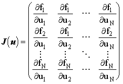 and and
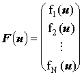 |
(2.84) |
This is more conveniently expressed as:
 where where |
(2.85) |
giving a new linear system with the Jacobian as the coefficient matrix. This may be solved by one of the standard linear solvers described above.
The relative ease with which the Jacobian may be generated (i.e. analytically) makes Newton's method very attractive, and hence it features as the main linearisation method in the electrochemical literature: by Balslev and Britz60, and Rudolph61 which serves as the basis for DigiSim(tm)45. Georgiadou and Alkire62 and also Yen and Chapman63 successfully used Newton's method to linearise the non-linear terms arising from migration.
However if the initial guess is too far from the solution, Newton's method may diverge, in which case more sophisticated globally-convergent methods may be required51,39. In the simulations conducted for this thesis, Newton's method was found to be adequate in all cases.
In the next chapter, methods for optimising the finite difference methods introduced here are discussed, together with methods for computing the current from the simulated concentration distribution.